PowerMill to MaxQ Dashboard workflow
How do you get from digital part to 3D printed part? In this article we will explain the workflow from Autodesk Powermill, a CAD/CAM software solution, to the MaxQ Dashboard, the operator dashboard developed by RAMLAB. This workflow instruction will guide you through creating toolpaths, editing, applying welding parameters, simulation, conversion to robot files for WAAM in PowerMill to starting and running a print job in the MaxQ Dashboard.
Step 1: Starting up PowerMill
Open PowerMill and load the preferred robot installation. Save the PowerMill project in the desired directory.
Step 2: Starting PowerShape
Open Powershape and model a surface plane and a block of desired dimensions. Place the surface plane and the block on separate levels.

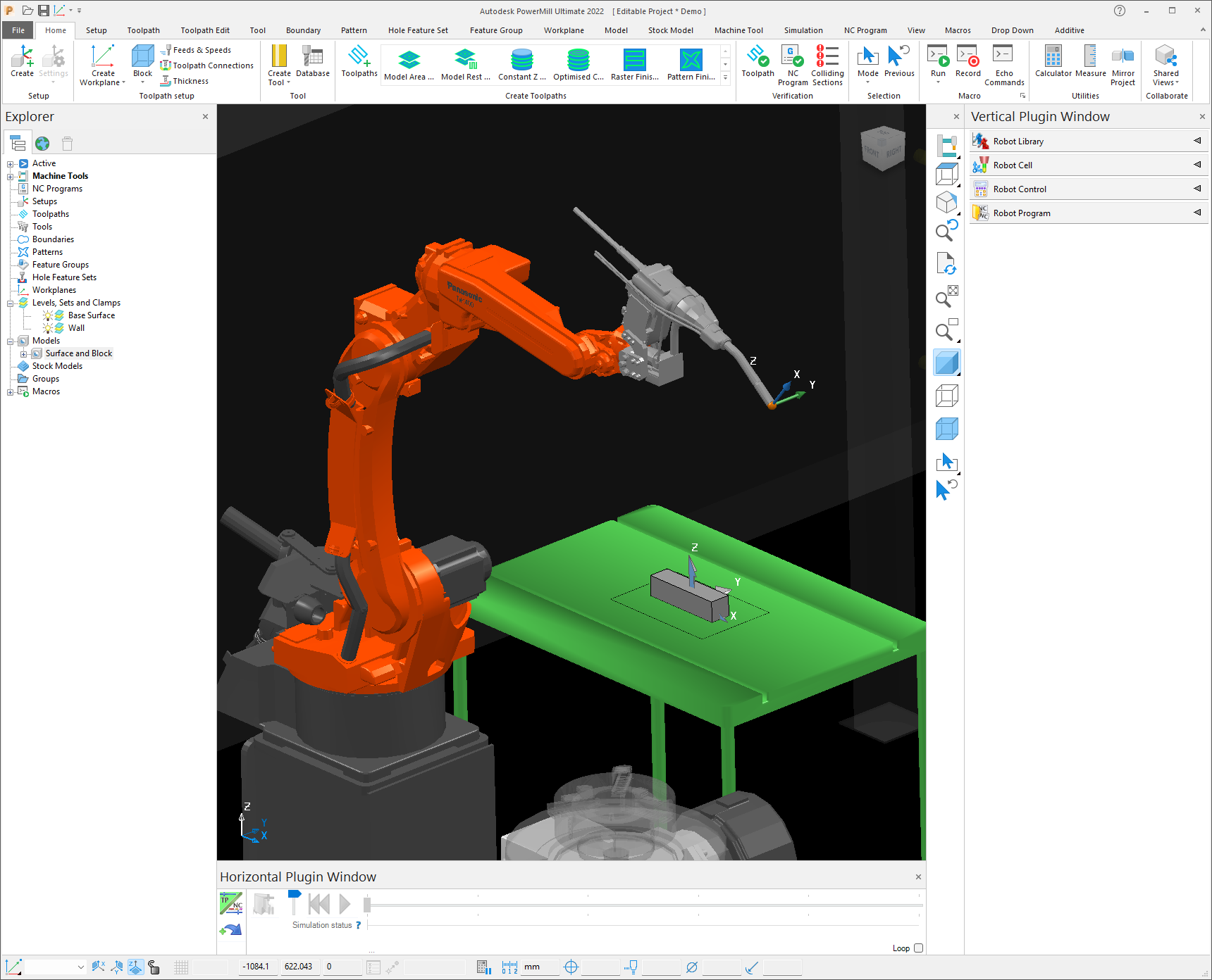
Step 3: Copy pasting models from PowerShape to PowerMill
Copy both the surface plane and block and paste it into PowerMill as a new Model by right clicking on the Model node of the Explorer tree. Now you should see the same levels as PowerShape in the Levels node of PowerMill.
Step 4: Generate additive toolpaths
Click on the button Feature Construction under the Additive Tab in PowerMill. A form as shown below will appear. Under the Surfaces drop down menu in the Base group select the surface plane and in the Feature group select the Wall. Enter the appropriate values for other parameters such as the stepover and step up in the Layering node. Once all parameters are entered, click calculate for PowerMill to generate the toolpaths for the wall.

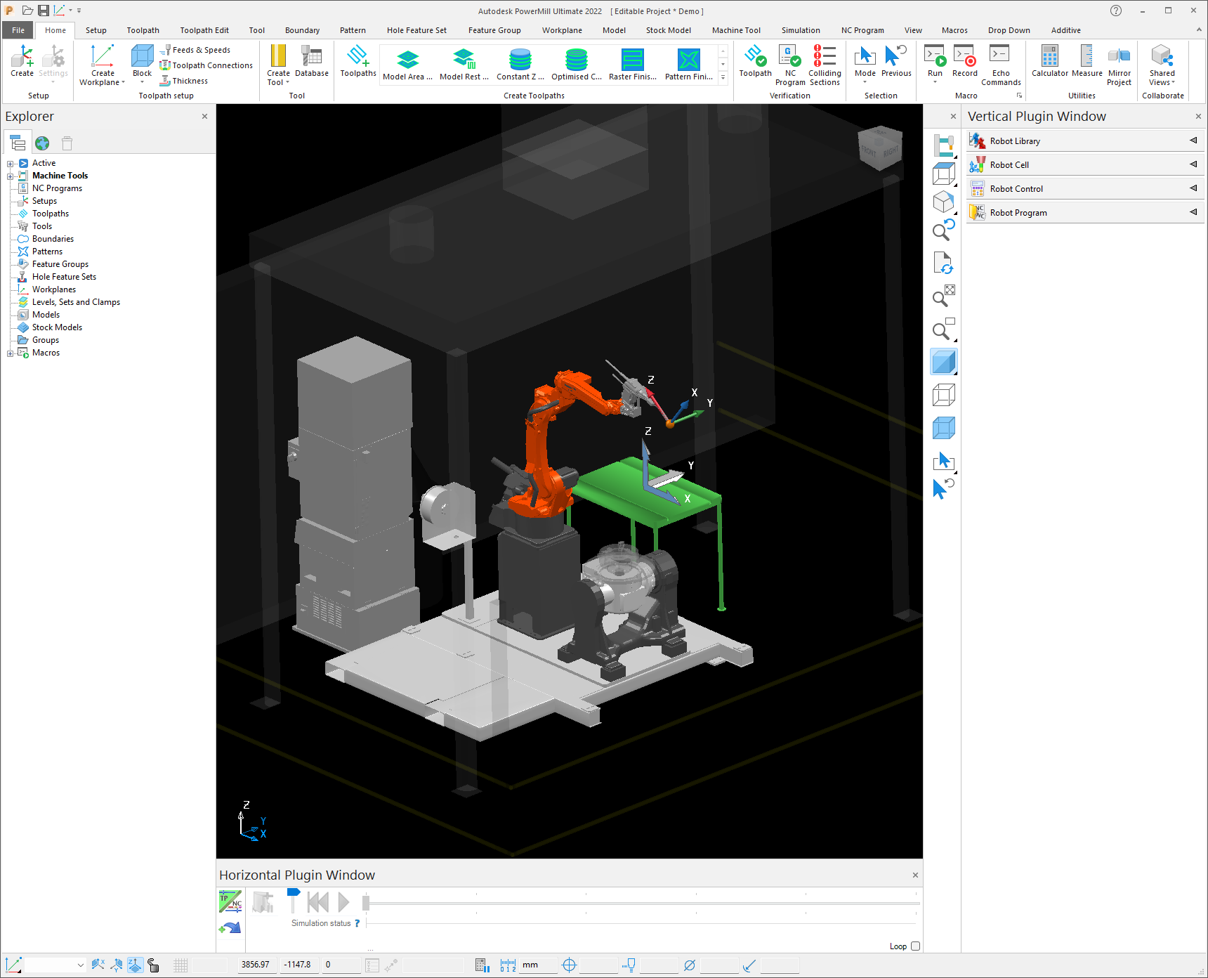
Step 5: View of the calculated toolpaths
The calculated toolpaths look like follows.

Step 6: View of individual layers
To individually look at each of the layers, click on View Layers under the additive tab.
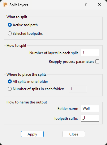
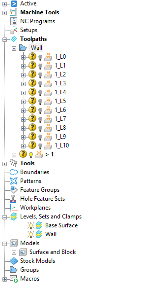
Step 7: Split the toolpath into individual layers
Split the layers into separate toolpath using the split layers button under the additive tab. The split layers can be seen under the folder “Wall” in the explorer tab.
Step 8: Renaming the split toolpaths appropriately
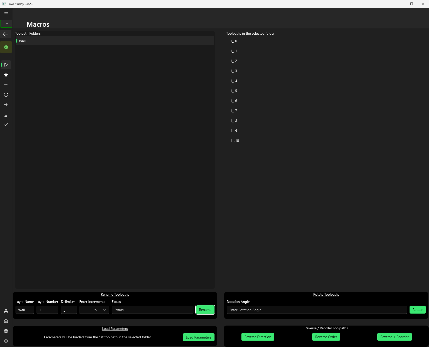
To rename the toolpaths, open RAMLAB PowerBuddy and connect to PowerMill. Navigate to the Macros tab in the left navigation pane. Click on the folder Wall to view the layers inside this folder. Under the Rename group at the bottom, enter the details and click on rename.
Step 9: Change the direction and order of the layers
To reverse the direction and/or the order of the toolpaths, click on the reverse + reorder button under the Reverse / Reorder Toolpaths group.

Step 10: Apply welding process parameters
Loading welding parameters from the database. In RAMLAB PowerBuddy, navigate to the process parameters tab in the navigation pane and click on the desired folder. After selecting the desired process parameters click on Apply Process parameters. The parameters will be applied to the start and end of each of the beads in the layers.

Step 11: Simulate the layers with the preferred robot
Now, with the loaded robot simulate the toolpaths to record all the parameters into a .RobSim file.

Step 12: Make an NC Program
Right click on the white space on the robot program pane on the right. Insert all the simulation files of the layers. Give an appropriate name to the NC Program. Finally, click on the Write robot NC program button to generate the robot readable files to be uploaded to the MaxQ Dashboard.

Step 13: Create a project and print file in the MaxQ Dashboard
In the MaxQ Dashboard, Navigate to the Prepare tab and create a new Project and Print File. Drag and drop the files created from PowerMill to the MaxQ Dashboard.

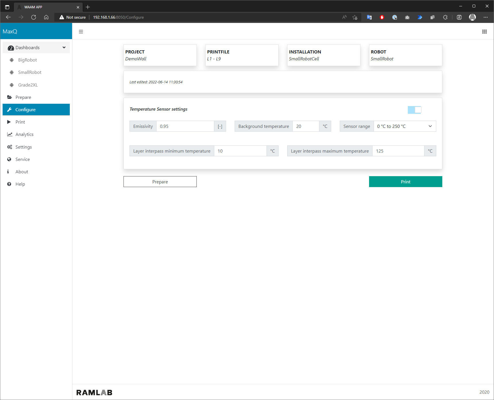
Step 14: Configure settings
Once the files have been converted, click on the Configure Setting button. Enter the appropriate settings for the temperature sensor.

Step 15: Start Job
Click on Print and perform all the checklists. Click on Start Job at the bottom.

Speak to an expert
Want to know more about creating toolpaths for WAAM? Leave your details to get in contact.
